CANnector EtherCAT
Advanced Configuration Tool
Freeware version
The Advanced Configuration Tool Free is the entry-level version of Ixxat’s ACT software for Windows® 10 and 11. It allows users to create gateway configurations for CANnector, FRC-EP, and Mobilizer devices using an intuitive drag & drop interface.
The freeware version is ideal for a large group of users and offers all of the modules listed below.
Gateway
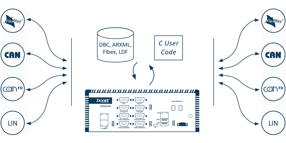
The gateway is the main application of every configuration being executed on the CANnector, Mobilizer or FRC-EP series. It is not only providing the data transfer from one CAN bus to another, it also allows to connect logical bus systems – like user code, data logger, Matlab/Simulink, etc. – to the overall data exchange. With this strategy it is possible to route every frame, PDU or signal individually from source to destination. This can be operated directly or for example via customized user code to manipulate the data on the fly.
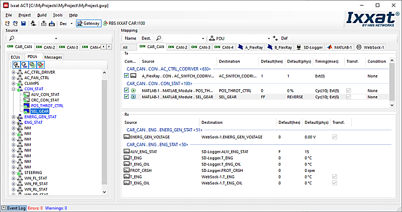
This is possible by using the Gateway view of the ACT tool and using drag & drop to define the relationship between source and destination. Just drag the desired data from the source bus and drop it on the destination - irrelevant whether this is a real bus system or the user code, logger or something else. At the end, the created configuration can be loaded on an Ixxat embedded platform and run stand-alone.
`
FlexRay, CAN, CAN FD & LIN
A bus description file can be provided for physical FlexRay, CAN, CAN FD and LIN bus systems. With the signal-based gateway, it is thereby possible to combine signals from different source messages into one target message.
- Free selection of send triggers and possible default values
- Optional automatic signal transformation – if the signal description of the source and target signal deviate from each other
- Cycle time adaptation of the sent messages to relieve the recipient connected to the target bus.
Analog & digital I/O
The FRC-EP and CANnector devices also provide analog or digital I/O ports. With ACT you can use these signals like any other signal in your configuration.
After configuring the data direction, range of values, conversion rules and units, the I / Os can be mapped easily via drag & drop. This makes it possible to map trigger inputs/outputs of the logger or to fill in vehicle signals based on analog inputs.
- Different IOs supported depending on the used embedded platform
- Easily added to the gateway as a virtual bus
Virtuele bus
By means of ACT you can add the virtual bus to your configuration. The virtual bus can be used to define your own “variables” (environment variables) in the configuration. These variables can be mapped via the drag & drop concept to/from any other bus system. This allows – for example – to calculate such a variable by your C user code module and then use it in any other bus system
DBC-generator
One functionality of the gateway is to generate DBC Files based on the mapping of the different physical and logical buses – for CAN, CAN FD, Generic Ethernet, virtual CANonEthernet, CAN@net.
Datalogger
Use ACT's data logging functionality to add data to the configuration. The logger bus is a 'logical' bus within ACT that can only receive data.
Any signal within the configuration - CAN (FD), LIN, FlexRay signal / frames, UserCode, etc. - can be assigned to the logger bus via drag & drop and then recorded to mass storage device, or the cloud, for later analysis . The logger supports:
- Register data in CSV, ASC, BLF or MDF format
- Using multiple recording groups to group the data that belongs together
- Using trigger signals to decide what to record and when
- Using a ring buffer system to also include data "before" a particular trigger occurs
- Decide whether to record a triggered event, cyclically or upon a signal change
- Use of analog and/or digital I/Os for manual triggering
- Use of the logger functionality alone or in combination with any other functionality running in parallel on the CANnector or FRC-EP series device
- Access the logger via web sockets in a browser
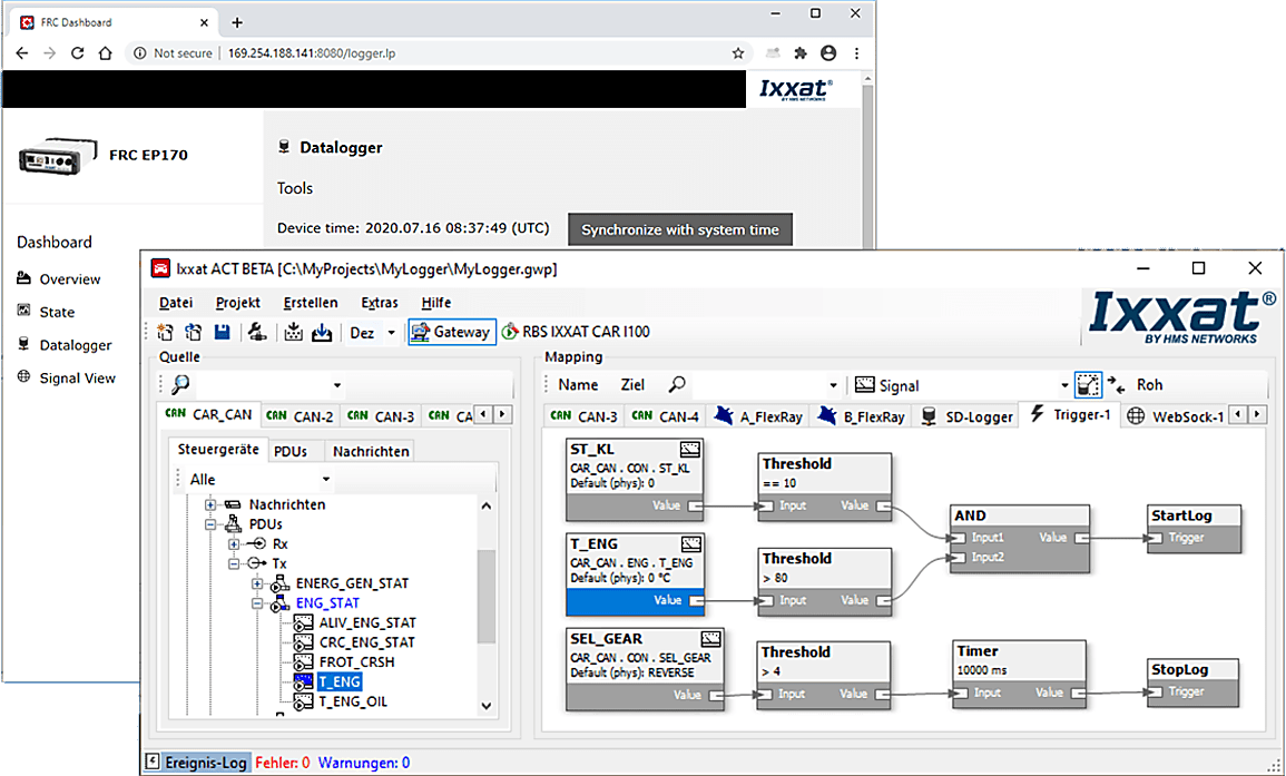
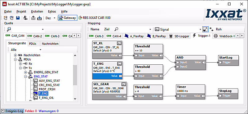
Trigger
The trigger is a further logical bus which can be added to the ACT configuration. When added, every signal within the configuration can be mapped to the trigger bus by means of the drag & drop concept and being used as input signal. The trigger engine can be designed in a graphical manner. Several functional blocks can be used:
- Timer
- Counter
- Thresholds
- Flip-flops
- Logical combinations
By connecting these blocks, you are enabled to define a trigger logic which is then resulting in trigger signals as output of the trigger engine. These outputs are normal signals like any other signal in the configuration. They can be used to:
- Trigger the data logger
- Drive the digital outputs of the CANnector or FRC-EP series device
- Trigger the transmission of a certain message
- Steer a binary signal on any physical bus system
- Steer a certain functionality in your UserCode
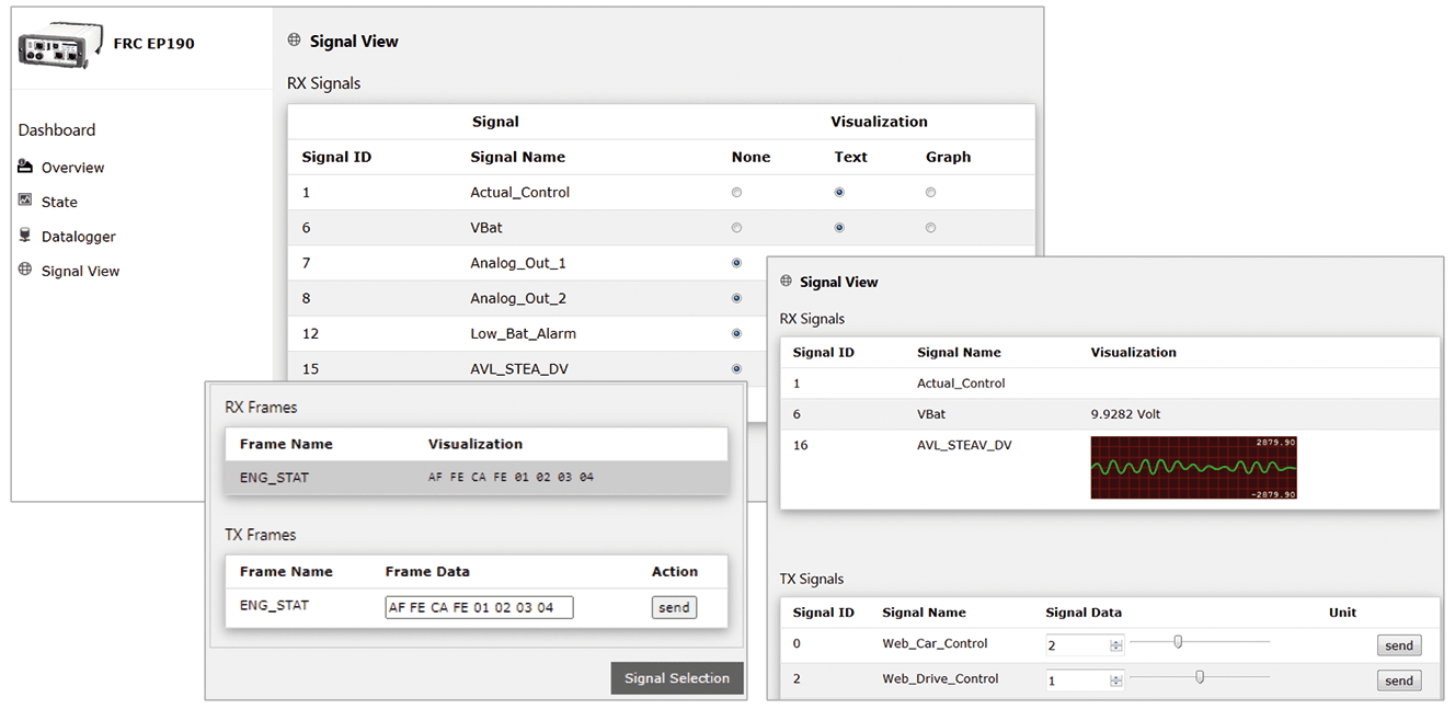
Visualization
The signal visualization is added as a virtual bus to the gateway configuration. It enables easy display and stimulation of all mapped signals via the integrated web server. Any device (PC, smartphone, tablet) can be used as a display device. The only basic requirement is an HTML5-capable web browser. HMS provides a generic HTML page for this. This can be adapted by the user to suit their own requirements. The visualization device is connected via USB, Ethernet or WLAN.
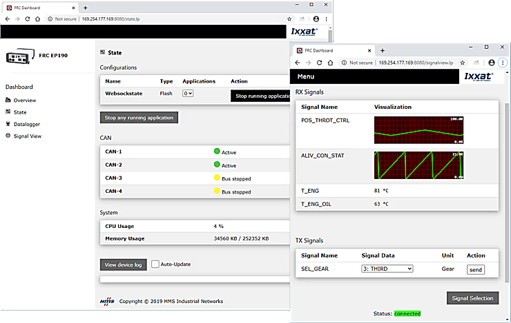
You can individually select which signals shall be visualized and whether they shall be displayed in textual or graphical form. Such a visualization configuration can be stored either on the CANnector/Mobilizer/FRC-EP series or the visualization device. This allows to store views individually or to define by the person having done the configuration what is allowed to be seen.
Do you want to have a specific visualization? If the default visualization is not sufficient, you can easily add your own HTML5 based visualization. You just need to connect to the standardized data exchange stream.
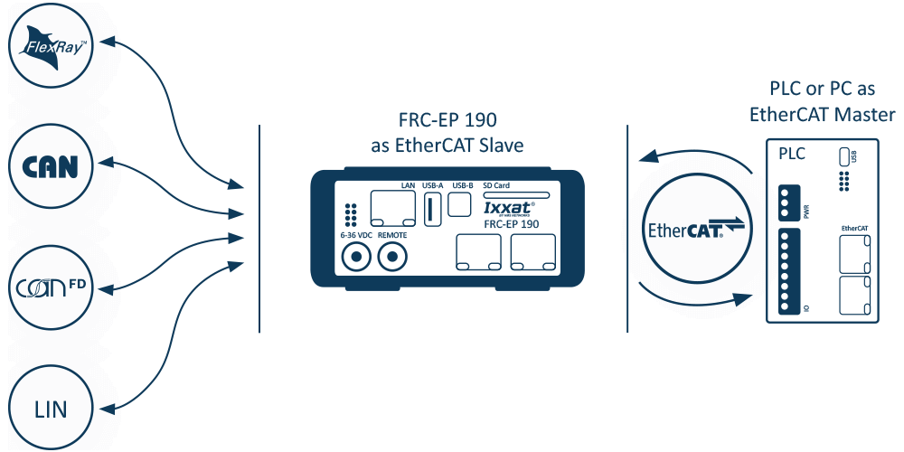
EtherCAT
This is available for CANnector or from a FRC-EP series device with an EtherCAT extension. Within ACT, simple drag & drop can then be used to generate mappings from / to the EtherCAT slave. ACT also automatically generates a corresponding ESI file that can be used together with any suitable EtherCAT master to conveniently configure your EtherCAT network.
Once connected to EtherCAT, all data - coming from the CAN (FD), Flexray or LIN bus system or from another EtherCAT based sensor or IO device - is synchronized and distributed on the same communication system to an PLC or Master Controller to facilitate test execution.
- EtherCAT extension allowing to combine automotive and industrial networks
- Easy signal selection for analysis and stimulation via EtherCAT by using ACT
- EtherCAT configuration can be read directly from the device
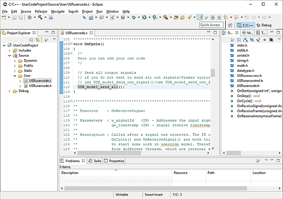
Development tool (UserCode)
ACT allows for many different configurations, but of course does not offer all possible functionality. In that case, a configuration can be extended with its own C user code.
An Eclipse-based development environment is available for the development of your own applications. Using this development environment, user code can be created for the extension of an ACT solution or for completely separate applications. ACT generates a C user code template that contains all the API to connect functions to the rest of the system. This is supported by the integration into the ACT project, the handy editor, cross compiler, as well as a high-level language debugger. The developed applications can be run stand-alone or on the Ixxat embedded systems.
Functional modela
For some users, the development of C code is too complex or there are already finished models from other projects. The integration of these models is possible via an API based on the user code bus. Similar to the user code, a Matlab/Simulink model can then access the mapped signals/messages.
- Easy implementation of own functions, e.g. for control of digital outputs or implementation of complex trigger modules for the logger
- User code bus added as a virtual bus to the the gateway configuration
- IO signals for own code mapped via drag & drop from and to all other bus systems
- User code application written in standard C and may represent also specific algorithms
- Eclipse-based SDK incl. remote debugger for developing and testing the application
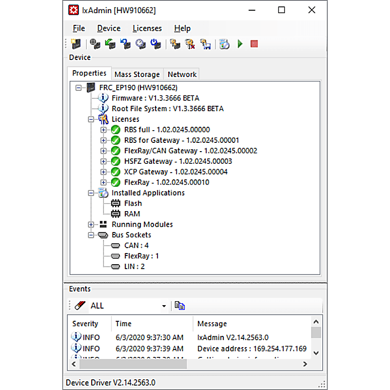
IxAdmin
IxAdmin is the PC based administration tool for the FRC-EP Series, Mobilizer and CANnector platform which can be connected via USB, Ethernet or WiFi.
- Up-/download of configurations
- Management of multiple configurations
- Execution of device updates
- Update firmware/board support package
- Runtime license management
- General settings
- Access to the web-based dashboard
- Access to logger files
- Also available as command line tool
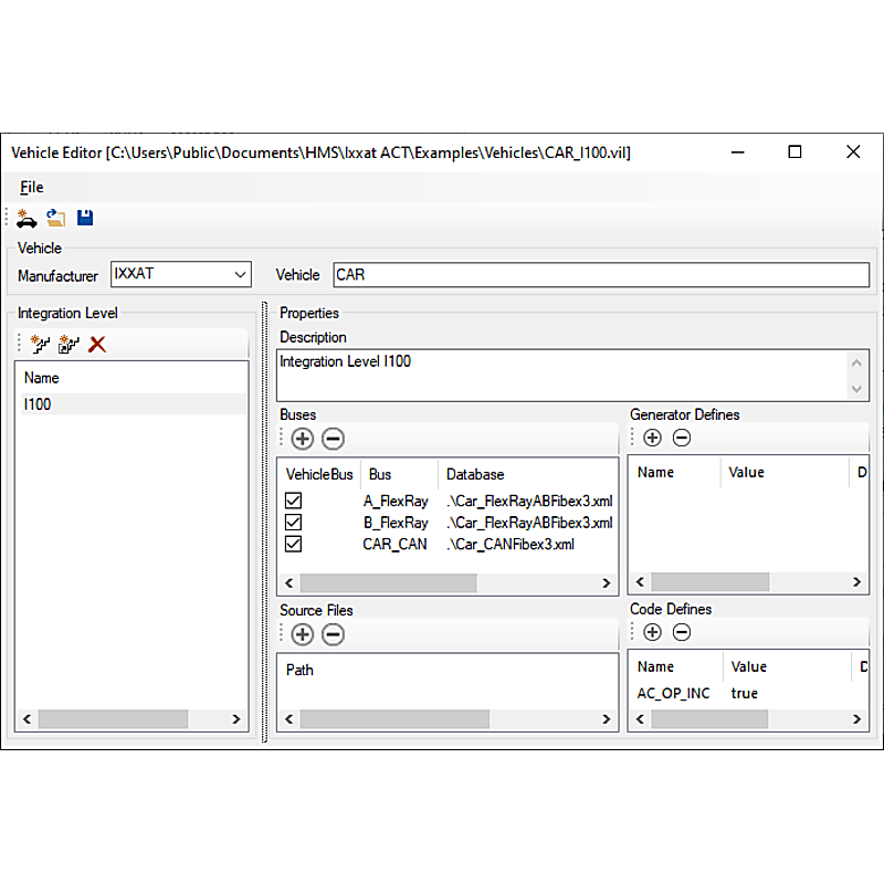
Vehicle Editor
The basis for most solutions are bus description files such as CANdB, DBC, LDF, FIBEX or AUTOSAR-XML. Normally, the descriptions contain a lot of information, but are missing important details like CRC, checksum or alive counter algorithms which are needed to generate e. g. a Residual Bus Simulation (RBS).
The Vehicle Editor allows to create a complete vehicle description database containing all information needed. In case of changes during the life cycle of your testing application (e. g. new vehicle integration levels), a new variant of such a vehicle description database can be created which then allows then an easy porting of existing residual bus or gateway configurations. This saves time and reduces the risk of introducing errors into already verified testing configurations.
CAN Bus Monitor
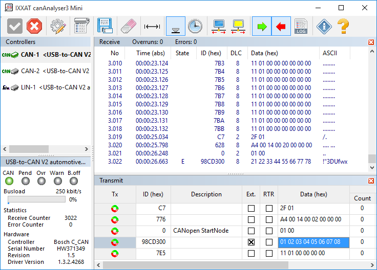
Ixxat canAnalyser 3 Mini
For simple testing purposes and start-up canAnalyser Mini - a free CAN bus monitor - is installed with the VCI. This monitor can be used to display CAN messages with time stamp, message identifiers and data using the CANnector EtherCAT. A logging function enables the data received to be recorded directly to hard disk. CAN messages are transmitted via a list wherein CAN messages are entered. Installed interfaces are displayed with the available CAN controllers, the current bus load and the controller status.
canAnalyser Mini also support CAN-FD and LIN in combination with interfaces supporting these protocols.
Common Driver
Ixxat CAN Interface Driver
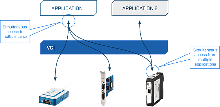
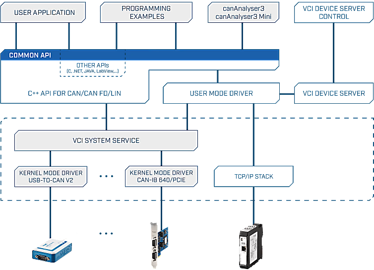
Two different drivers are available for the software interfacing of the CANnector EtherCAT: the universal driver "(Virtual Communication Interface" (VCI) for Windows® and the “Embedded Communication Interface” (ECI) for Linux, INtime, RTX, VxWorks and QNX. The drivers can operate all CAN channels and all CAN interfaces - even different types - within one PC.
These powerful driver packages support all CAN boards, regardless of their PC interface, with a uniform programming interface (API). This means that applications based on VCI-API can be used with all Ixxat CAN boards without modifying the application program. The drivers support multi CAN-channels and/or multiple boards – even different types – to arrange the desired amount of channels.
Features and benefits
- Common application programming interface (API) for all supported operating systems and interfaces
- Simultaneous support of multiple CAN channels and interface boards
- Standard (11 bit, CAN 2.0A), extended protocol (29 bit, CAN 2.0B) and CAN-FD1
- Support of protocol-switching on interfaces with low-speed CAN1 or LIN1
- Slim communication interface while supporting all required mechanisms for an easy operation of the interface
- Detection and display of error frames on the bus
- Measurement and display of the bus load (only with active CAN cards)
- Possible operation in "Listen only mode" 1 For interfaces that support these protocols
Virtual Communication Interface (VCI)
- Fee driver for CAN interfaces under Windows® 2000, XP, Vista, 7, 8 and 10.
- Application interfaces available for C++, .NETI, Java, LabView, DasyLab and LabWindows
- Convenient card installation via the Device Manager
- Prepared dialog for interface/channel selection
- Automatic firmware download with active cards
Embedded Communication Interface (ECI)
- Free driver for active and passive CAN interfaces under Linux, INtime, RTX, VxWorks and QNX.
- Application interfaces available for C and a vendor-independent API called SocketCAN
- Low memory footprint
- Specially suitable for dedicated embedded applications
- Real-time capable (INtime, RTX, VxWorks and QNX)
Programming environment
Ixxat VCI API
The VCI API (Application Programming Interface) is a powerful software library that enables developers to easily communicate with industrial network interfaces, particularly within CAN- and/or LIN-based systems. This API forms an abstraction layer between applications and hardware, allowing developers to avoid working directly with device-specific drivers and instead utilize a uniform and standardized interface.
With the VCI API, applications can send and receive CAN messages in both standard and extended formats. Additionally, the API enables the detection, configuration, and management of connected Ixxat devices. Developers can choose between event-driven communication or polling mechanisms, depending on their application requirements. Thanks to built-in buffering and filtering capabilities, data can be processed efficiently, which is particularly important in real-time environments.
The API is primarily available for programming languages such as C and C++, with additional support for .NET languages via wrappers. This makes the VCI API widely applicable within both low-level and high-level development environments.