


Mobilizer Pro 822 EtherCAT
The Ixxat Mobilizer Pro 822 EtherCAT is an advanced and powerful computing gateway with a wide range of interfaces. First and foremost, the device seamlessly integrates various bus systems into a single solution. This makes the system ideal for complex logging and stimulation applications. The gateway features a FlexRay A/B channel and eight CAN FD/CAN channels. In addition, the device supports Ethernet, two LIN channels and two SENT channels. Furthermore, four analogue inputs, two analogue outputs and six digital I/Os are available. This variant also includes an EtherCAT slave interface for centralised control. This enables, for example, automatic test and measurement processes to be implemented efficiently.
The Mobilizer Pro 822 EtherCAT is also a powerful embedded communication and test solution for automotive applications. The system has been developed to meet the high communication and testing requirements of modern vehicle networks. Furthermore, the device combines high performance with maximum flexibility and a robust hardware design. At the same time, user-friendly software tools ensure efficient configuration and operation. The system acts as a central hub where multiple networks converge. This allows data to be intelligently processed, combined or routed. The gateway supports CAN, CAN FD, LIN and other available networks. The system also processes data from external USB devices and analogue or digital inputs.
The computing gateway also offers six main functionalities: Data Logging, Diagnostics, Gateway, Residual Bus Simulation, Range and Visualisation. These functions can be easily configured or combined using the supplied ACT software. This creates a flexible solution for a wide range of automotive test environments. In short, the Mobilizer Pro 822 EtherCAT offers a comprehensive solution for advanced communication, testing and automation applications.
The Mobilizer Pro 822 EtherCAT is supported by the Ixxat ACT (Advanced Configuration Tool). This Windows®-based configuration tool is easy to use via drag & drop. This allows complex configurations to be put together quickly. Furthermore, users can handle most applications using the freeware edition of the ACT software. This keeps implementation straightforward and cost-effective.
Endless features, One solution
Intelligent gateways from HMS offer a variety of integrated applications that can be configured with just a few clicks. Once configured, they work standalone without additional software or hardware, unlike conventional solutions. Users do not have to choose a single application, but can set up and run several applications in parallel on one gateway – in the shortest possible time and without any programming knowledge.
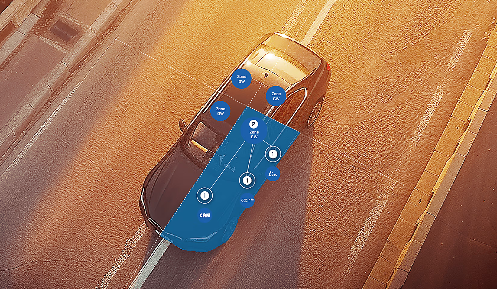
Domain or zone architecture?
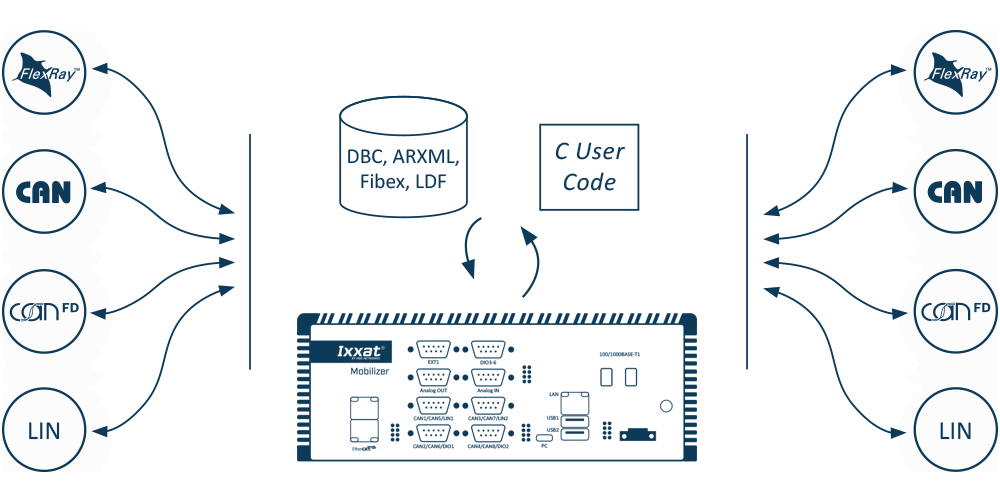
Since modern electronic components in automobiles require centralized data processing, many car manufacturers are switching from the established domain architecture to a zonal E/E architecture. Regardless of this, the intelligent gateways of the Mobilizer, CANnector and FRC-EP families are suitable for solving communication applications in both system environments - regardless of their architecture. In addition, the HMS gateways support all common on-board networks and their message catalogs such as Fibex, DBC, ARXML, A2L or LDF.
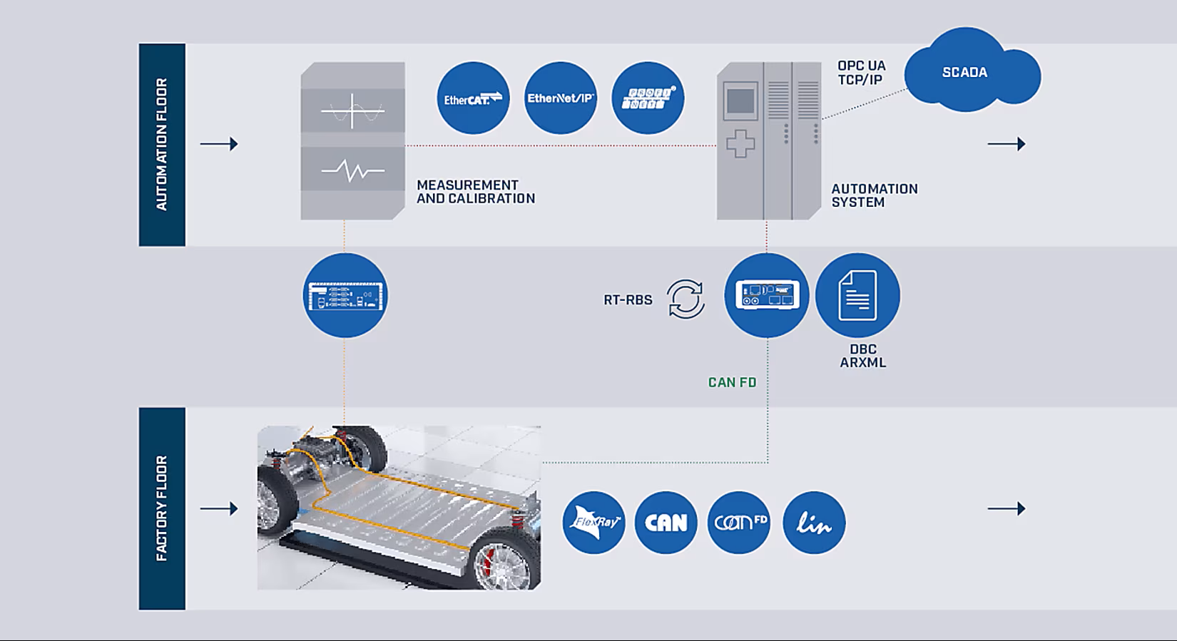
Automation and PLC interoperability
Communication tasks between in-vehicle communication in the vehicle and factory automation often require several hardware and software components, which means a significant amount of time and money. The intelligent gateways of the Mobilizer, CANnector and FRC-EP series facilitate access to the network in the vehicle for communication, diagnostics and flashing, thereby closing the gap between factory automation and vehicle communication safely and reliably.
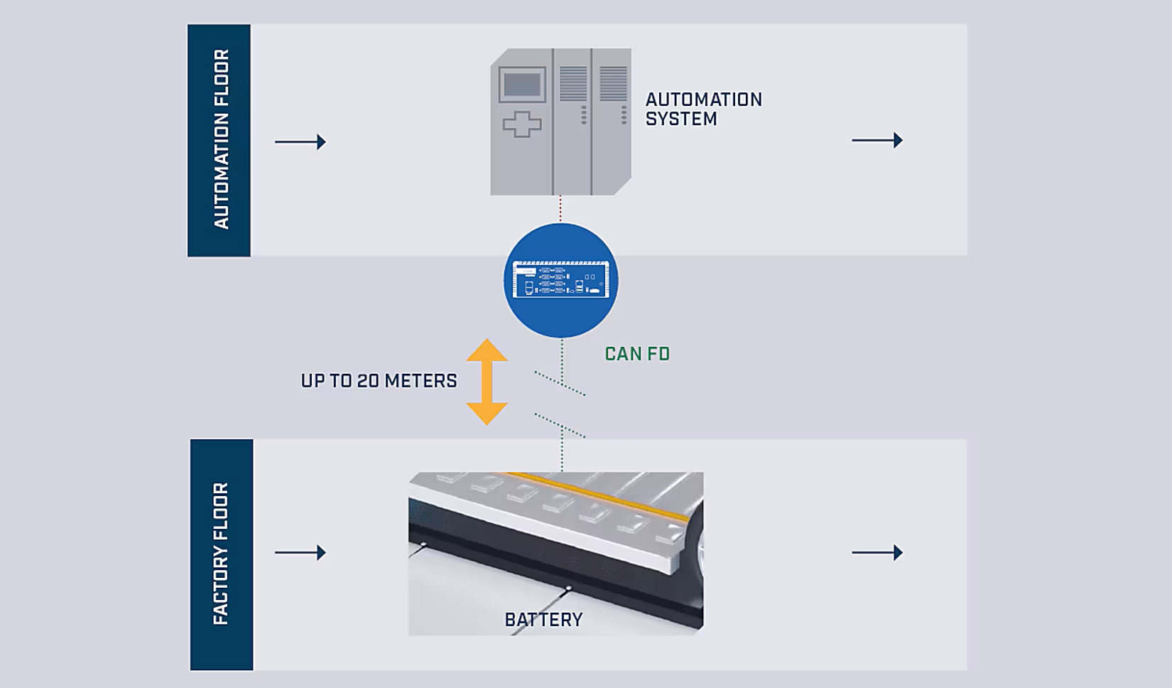
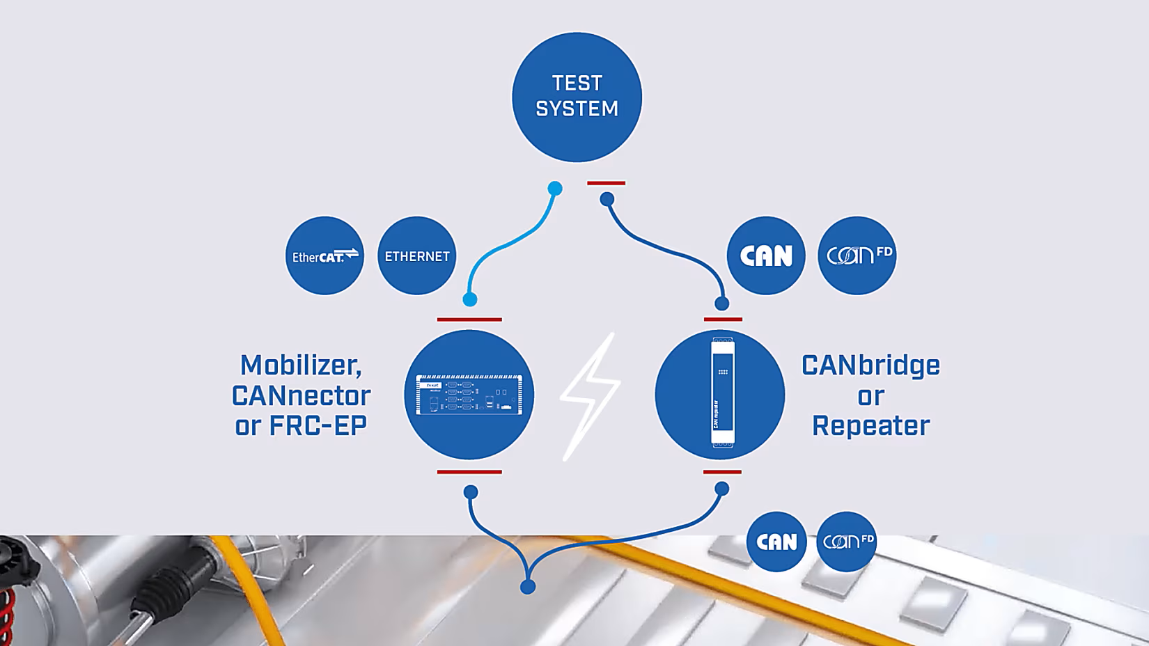
CAN Range Extension
Intelligent gateways enable the wired or wireless connection of test benches, test objects and test/simulation tools via CAN/FD over longer distances. Ixxat offers scalable solutions for range extension - from simple non-intelligent repeaters for CAN/CAN FD for segmentation or galvanic isolation to intelligent bridges and powerful platforms that support many different bus systems and offer conversion and interpretation functions.
Overvoltage & EMI protection
In automotive production lines, vehicle components such as engines, drives or batteries are tested under high voltage conditions. This means that all connected test components are also exposed to high voltages. The Computing Ggateways and all CAN repeaters have integrated galvanic isolation that protects all system components from high voltage and electromagnetic interference (EMI), between one and four kilovolts.
Functionality
Thanks to a powerful i.MX 8M Plus Quad-Core powered Linux platform, Mobilizer is capable of executing highly complex applications and data manipulations directly on the device. Support for DBC files also makes it possible to work at the signal level. The Mobilizer enables easy integration of multiple bus systems into a single, compact device. This is essential for e-mobility projects and complex industrial applications.
The system features 8 CAN FD channels; furthermore, it includes 2x LIN, 1x Ethernet (10/100 Base-T), up to 4x Digital Input/Output, 1x USB Device, 2x USB Host, and SDHC.
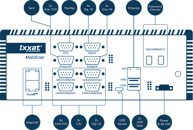
This Pro variant also features FlexRay, 2x Automotive Ethernet, EtherCAT, 2x SENT, 4x Analog Input and 2x Output, and K-line*.
Advanced Configuration Tool
Freeware version
The Advanced Configuration Tool Free is the entry-level version of Ixxat’s ACT software for Windows® 10 and 11. It allows users to create gateway configurations for CANnector, FRC-EP, and Mobilizer devices using an intuitive drag & drop interface.
The freeware version is ideal for a large group of users and offers all of the modules listed below.
Gateway
The gateway is the main application of every configuration being executed on the CANnector, Mobilizer or FRC-EP series. It is not only providing the data transfer from one CAN bus to another, it also allows to connect logical bus systems – like user code, data logger, Matlab/Simulink, etc. – to the overall data exchange. With this strategy it is possible to route every frame, PDU or signal individually from source to destination. This can be operated directly or for example via customized user code to manipulate the data on the fly.
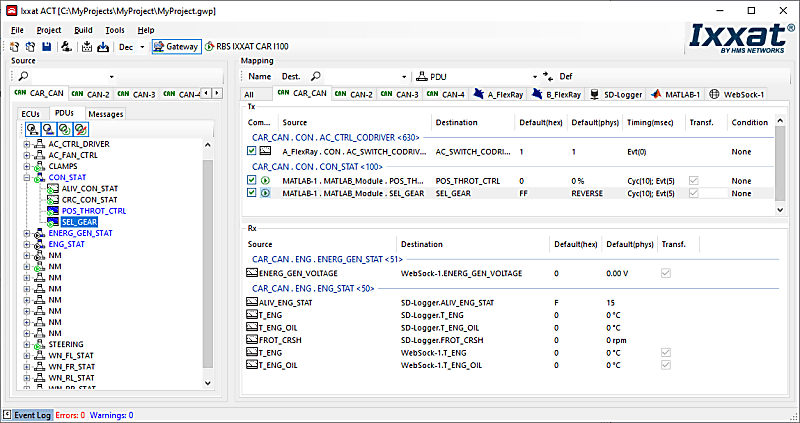
This is possible by using the Gateway view of the ACT tool and using drag & drop to define the relationship between source and destination. Just drag the desired data from the source bus and drop it on the destination - irrelevant whether this is a real bus system or the user code, logger or something else. At the end, the created configuration can be loaded on an Ixxat embedded platform and run stand-alone.
`
FlexRay, CAN, CAN FD & LIN
A bus description file can be provided for physical FlexRay, CAN, CAN FD and LIN bus systems. With the signal-based gateway, it is thereby possible to combine signals from different source messages into one target message.
- Free selection of send triggers and possible default values
- Optional automatic signal transformation – if the signal description of the source and target signal deviate from each other
- Cycle time adaptation of the sent messages to relieve the recipient connected to the target bus.
Analog & digital I/O
The FRC-EP and CANnector devices also provide analog or digital I/O ports. With ACT you can use these signals like any other signal in your configuration.
After configuring the data direction, range of values, conversion rules and units, the I / Os can be mapped easily via drag & drop. This makes it possible to map trigger inputs/outputs of the logger or to fill in vehicle signals based on analog inputs.
- Different IOs supported depending on the used embedded platform
- Easily added to the gateway as a virtual bus
Virtuele bus
By means of ACT you can add the virtual bus to your configuration. The virtual bus can be used to define your own “variables” (environment variables) in the configuration. These variables can be mapped via the drag & drop concept to/from any other bus system. This allows – for example – to calculate such a variable by your C user code module and then use it in any other bus system
DBC-generator
One functionality of the gateway is to generate DBC Files based on the mapping of the different physical and logical buses – for CAN, CAN FD, Generic Ethernet, virtual CANonEthernet, CAN@net.
Datalogger
Use ACT's data logging functionality to add data to the configuration. The logger bus is a 'logical' bus within ACT that can only receive data.
Any signal within the configuration - CAN (FD), LIN, FlexRay signal / frames, UserCode, etc. - can be assigned to the logger bus via drag & drop and then recorded to mass storage device, or the cloud, for later analysis . The logger supports:
- Register data in CSV, ASC, BLF or MDF format
- Using multiple recording groups to group the data that belongs together
- Using trigger signals to decide what to record and when
- Using a ring buffer system to also include data "before" a particular trigger occurs
- Decide whether to record a triggered event, cyclically or upon a signal change
- Use of analog and/or digital I/Os for manual triggering
- Use of the logger functionality alone or in combination with any other functionality running in parallel on the CANnector or FRC-EP series device
- Access the logger via web sockets in a browser
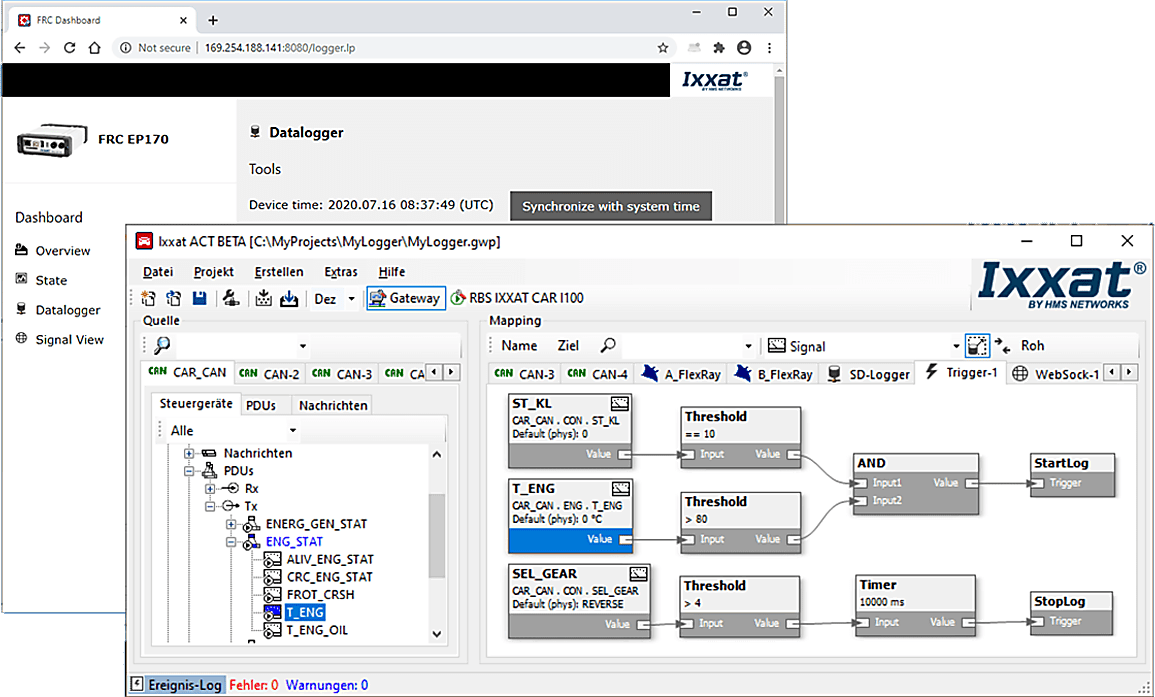
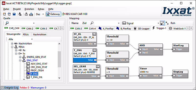
Trigger
The trigger is a further logical bus which can be added to the ACT configuration. When added, every signal within the configuration can be mapped to the trigger bus by means of the drag & drop concept and being used as input signal. The trigger engine can be designed in a graphical manner. Several functional blocks can be used:
- Timer
- Counter
- Thresholds
- Flip-flops
- Logical combinations
By connecting these blocks, you are enabled to define a trigger logic which is then resulting in trigger signals as output of the trigger engine. These outputs are normal signals like any other signal in the configuration. They can be used to:
- Trigger the data logger
- Drive the digital outputs of the CANnector or FRC-EP series device
- Trigger the transmission of a certain message
- Steer a binary signal on any physical bus system
- Steer a certain functionality in your UserCode
Visualization
The signal visualization is added as a virtual bus to the gateway configuration. It enables easy display and stimulation of all mapped signals via the integrated web server. Any device (PC, smartphone, tablet) can be used as a display device. The only basic requirement is an HTML5-capable web browser. HMS provides a generic HTML page for this. This can be adapted by the user to suit their own requirements. The visualization device is connected via USB, Ethernet or WLAN.
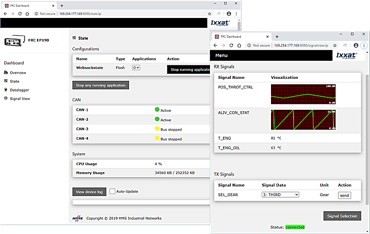
You can individually select which signals shall be visualized and whether they shall be displayed in textual or graphical form. Such a visualization configuration can be stored either on the CANnector/Mobilizer/FRC-EP series or the visualization device. This allows to store views individually or to define by the person having done the configuration what is allowed to be seen.
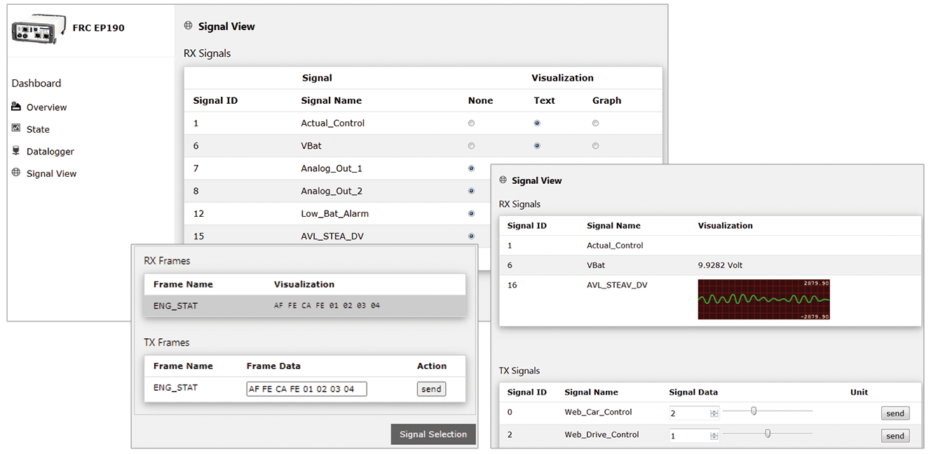
Do you want to have a specific visualization? If the default visualization is not sufficient, you can easily add your own HTML5 based visualization. You just need to connect to the standardized data exchange stream.
EtherCAT
This is available for CANnector or from a FRC-EP series device with an EtherCAT extension. Within ACT, simple drag & drop can then be used to generate mappings from / to the EtherCAT slave. ACT also automatically generates a corresponding ESI file that can be used together with any suitable EtherCAT master to conveniently configure your EtherCAT network.
Once connected to EtherCAT, all data - coming from the CAN (FD), Flexray or LIN bus system or from another EtherCAT based sensor or IO device - is synchronized and distributed on the same communication system to an PLC or Master Controller to facilitate test execution.
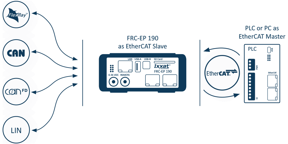
- EtherCAT extension allowing to combine automotive and industrial networks
- Easy signal selection for analysis and stimulation via EtherCAT by using ACT
- EtherCAT configuration can be read directly from the device
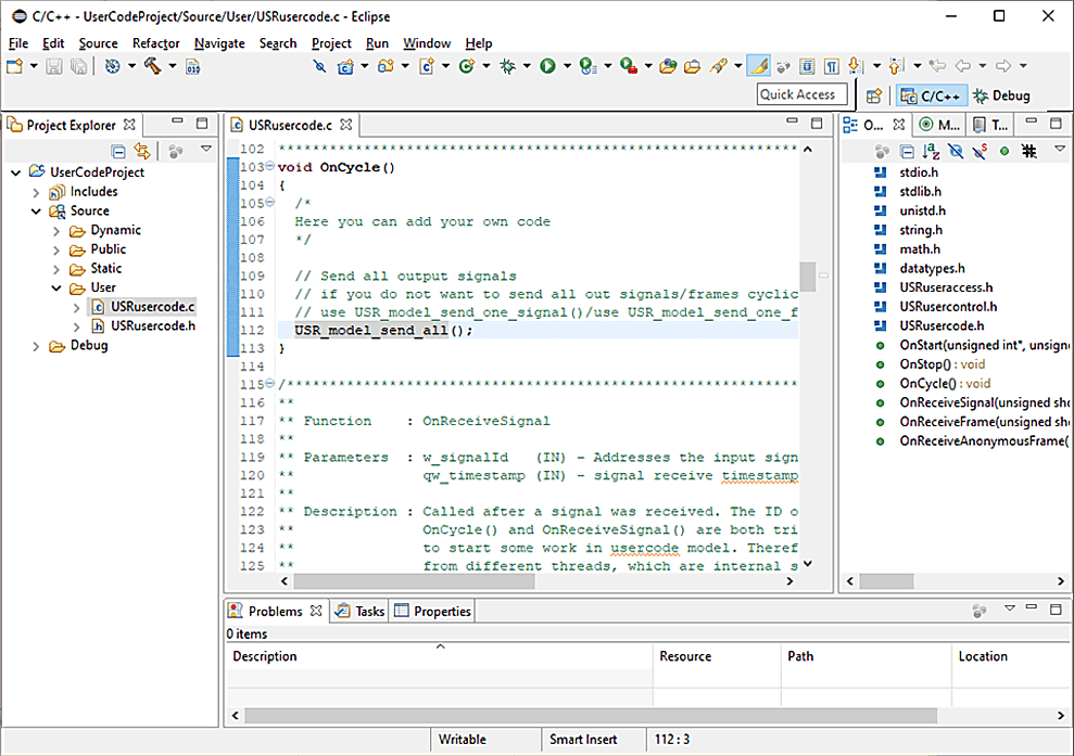
Development tool (UserCode)
ACT allows for many different configurations, but of course does not offer all possible functionality. In that case, a configuration can be extended with its own C user code.
An Eclipse-based development environment is available for the development of your own applications. Using this development environment, user code can be created for the extension of an ACT solution or for completely separate applications. ACT generates a C user code template that contains all the API to connect functions to the rest of the system. This is supported by the integration into the ACT project, the handy editor, cross compiler, as well as a high-level language debugger. The developed applications can be run stand-alone or on the Ixxat embedded systems.
Functional modela
For some users, the development of C code is too complex or there are already finished models from other projects. The integration of these models is possible via an API based on the user code bus. Similar to the user code, a Matlab/Simulink model can then access the mapped signals/messages.
- Easy implementation of own functions, e.g. for control of digital outputs or implementation of complex trigger modules for the logger
- User code bus added as a virtual bus to the the gateway configuration
- IO signals for own code mapped via drag & drop from and to all other bus systems
- User code application written in standard C and may represent also specific algorithms
- Eclipse-based SDK incl. remote debugger for developing and testing the application
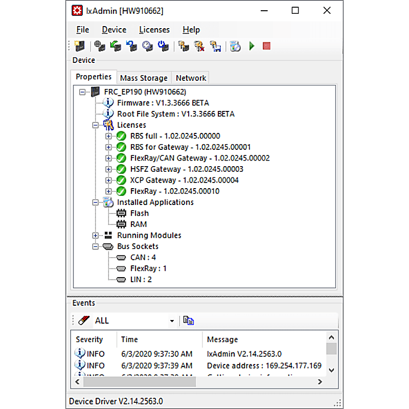
IxAdmin
IxAdmin is the PC based administration tool for the FRC-EP Series, Mobilizer and CANnector platform which can be connected via USB, Ethernet or WiFi.
- Up-/download of configurations
- Management of multiple configurations
- Execution of device updates
- Update firmware/board support package
- Runtime license management
- General settings
- Access to the web-based dashboard
- Access to logger files
- Also available as command line tool
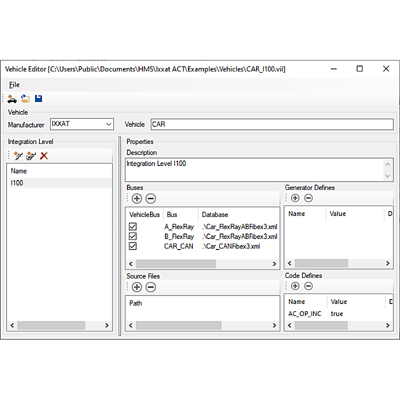
Vehicle Editor
The basis for most solutions are bus description files such as CANdB, DBC, LDF, FIBEX or AUTOSAR-XML. Normally, the descriptions contain a lot of information, but are missing important details like CRC, checksum or alive counter algorithms which are needed to generate e. g. a Residual Bus Simulation (RBS).
The Vehicle Editor allows to create a complete vehicle description database containing all information needed. In case of changes during the life cycle of your testing application (e. g. new vehicle integration levels), a new variant of such a vehicle description database can be created which then allows then an easy porting of existing residual bus or gateway configurations. This saves time and reduces the risk of introducing errors into already verified testing configurations.


