The CAN specialist
-Hidden- -Hidden-
Nederlandse taal English language
Skip to main content

CAN Bus Tester 2

Powerful tool for analysis of physical CAN bus systems

Rental only


The Ixxat CAN Bus Tester 2 supports the CAN protocol
The Ixxat CAN Bus Tester 2 supports the CANopen protocol
The Ixxat CAN Bus Tester 2 supports the J1939 protocol
CAN Bus Tester 2by Ixxat

Request for quote

Ask a question

The Ixxat CAN Bus Tester 2 (CBT2) tests the CAN bus hardware-wise and examines, among other things, the signal level on the bus, the electrical properties, and the specific CAN error messages. This makes it possible to measure the signal conditions exactly per network node and thereby locate hardware faults in the electronics and cabling. With an additional CANopen module, the CBT2 also monitors CANopen error messages. The accompanying example shows a current measurement of a CANopen node. This works similarly with J1939 or DeviceNet.

The CBT2 is a typical tester for checking the CAN bus in operation; the tester plays a role when standard analysis options (such as with the CAN Analyser) have not led to a solution.

Rental Service

The CAN Bus Tester 2 is rented out including remote support and problem analysis by Twincomm. The minimum rental period is 2 weeks, but can be extended by the week.


Features and benefits

  • Support of CAN, CANopen and SAE J1939 systems 
  • Analysis of the signal-to-noise ratio of all telegrams (level, flanks, faults)
  • Integrated oscilloscope with data interpretation for telegram analysis
  • Comprehensive trigger conditions for fault localization (logical and physical errors)
  • Monitoring of bus status, bus load, error telegrams
  • Wiring test (termination resistance, short circuits, interruptions, loop resistance, line length)
  • Automatic baud rate detection
  • Simple connection to CAN systems thanks to automatic baud rate detection and BusScan
  • Simple operation via Windows program
  • Simple generation of test protocols
  • CAN monitor for transmission and reception of CAN messages
  • RS-232 with direct microcontroller access
  • Soldering fields for individual additional wiring

Tech Specs

Controller

CAN CC (Classic CAN 2.0A/B)

CAN Mode

CAN high-speed (ISO 11898-2)

CAN Baudrates

5 kBit/s … 1 Mbit/s

Connector

D-Sub9 (CiA® 106)

Bit scanning

Bit scanning

Trigger uitgang

Trigger output

Power Supply

9~36 V=

Current Consumption

max. 550 mA

Temperature

Usage +5 °C to +40 °C
Storage -20 °C to +60 °C

Dimensions

504 x 354 x 119 mm

CAN Bus Tester 2

Physical CAN bus analysis

The CBT2 is a universal measuring instrument for commissioning, analyzing, monitoring, troubleshooting, and maintaining CAN bus systems. Typical malfunctions during the use of CAN bus systems, such as node failures, communication errors, or complete system failures, are often caused by a problem in the bus physics. In general, instruments that transmit messages with low signal quality are more prone to malfunctions. The CAN Bus Tester provides an overview of the signal conditions in the bus, allowing common causes of malfunctions to be quickly identified and corrected.
Furthermore, the most important logical analysis functions, which are normally only found in protocol analyzers, are also integrated into the Tester. The Tester can be used for all bus systems with 11 or 29-bit identifiers according to ISO 11898-2.

Automatic detection of the transmission speed and the self-connecting BusScan ensure that the CAN Bus Tester can be quickly and easily connected to the system to be analyzed. The measurement results are automatically assigned to the relevant CAN identifiers or network nodes.

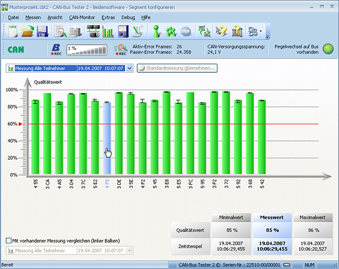
The CBT2 can measure and display the signal conditions of each CAN bus station. Any problems with the appropriate station or with the bus cabling can be inferred from the results of the signal quality. The CBT2 displays the following physical properties for each CAN bus station separately:

  • General quality level (0-100  1/li>
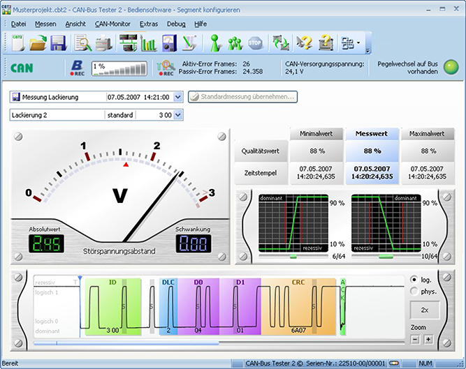
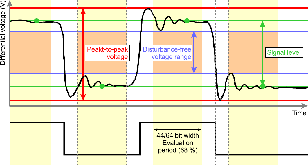
  • Disturbance-free voltage range (minimum, interference-free differential voltage)
  • Edge steepness (worst rising and falling edges of the message frame)
  • Oscilloscope display with frame analysis for the complete message frame
CAN Bus Tester 2 Screens (click for enlargement)

Searching for faults

Typical faults during the operation of CAN bus systems, such as node failure, communication errors or complete system failure, are often caused by problems in the bus physics. Generally, devices which transmit messages with a low signal-to-noise ratio are highly susceptible to failures. The CAN-Bus-Tester provides an overview of the signal-to-noise ratios on the bus, enabling frequent causes of failures to be quickly identified and rectified.

Measuring

The CBT primarily examines the interference-free range. This is the range that can be determined on the physical CAN bus between a zero and one level. The greater the difference—the distance—between both values, the better the CAN bus will function.
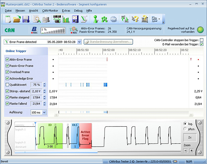
Testing

Depending on the test strategy, various methods of identifying faults can be used, such as a fast overview of the complete system, monitoring of an individual node or setting various trigger events (physical and/or logical faults and error-frames). When the trigger function is used, all faults are defined up to the individual bit position, are provided with a time stamp and displayed in the integrated oscilloscope. A trigger signal available via the external trigger output can be used to trigger an oscilloscope. A certain CAN message or an error telegram can thus be displayed selectively on the oscilloscope.

CANopen and J1939

The CBT2 also supports CANopen and J1939 using the included add-ons. The CBT2 utilizes the station layout and error handling that these higher protocols possess. This allows information sent from the same node to be combined.

FAQ

  • Can I order on account?

    Yes, that's definitely possible! Most customers place their orders through a Purchase Order.
    First request a quote and then send the purchase order (PO) by email, simply from your own purchasing system. For first time buyers, we may ask additional questions in order to perform a credit check. Please contact us if you require our company details for registration in the purchasing system.

    For security reasons, customers located in, or wishing to ship to, countries outside the Benelux must always pay in advance.

  • Why are all prices available upon request?

    The online webshop is still under construction. As soon as it is available, all prices will naturally be visible.

    However, everything is of course available, and we would be happy to inform you about prices and delivery times. Please contact us or give us a call. We have over 30 years of experience with CAN. We are happy to help you and offer you immediate practical advice or support.


Part number(s)

1.14.0402.99999 CAN Bus Tester 2
1x CAN
Country of Origin: Germany
HS Code: 8517620000

System requirements

  • Windows® (x32) 7, 8, 10 or 11
  • Vrije USB-poort voor interface (USB 2.0)

Scope of Supply

CAN Bus Tester 2
  • User Manual 1
  • Windows® software 2
  • CAN bus accessories
    - 6 adapter cables: SUB-D, Open style, M12, 7/8”, SAE J1939-11, SAE-J1939-13
    - Shorting plug: SUB-D, Open style, M12, 7/8”, SAE J1939-11
    - Termination resistor: SUB-D, M12, 7/8”, SAE J1939-11
    - T- or Y-adapter: M12, 7/8”, SAE J1939-11
  • Power unit 100-240 V~ / 50-60 Hz to 24 V, 500 mA, power cable
  • BNC cable
  • USB cable
  • CD met USB-driver en applicatie software
  • Alles in robuuste en afsluitbare koffer
1 Available as PDF
2 All software available by download

Interested?

Are you interested in the CAN Bus Tester 2? Request a quote without obligation. Would you like more information? Send an email to -Hidden- or visit our contact page. You can also call us at -Hidden-.
Twincomm has over 30 years of experience with CAN. We are happy to help you and offer you immediate practical advice or support.