PCAN-MicroMod FD Evaluation Board
On request
Request for quote
Ask a question
This Peak PCAN-MicroMod FD Evaluation Board has been specially developed for the PCAN-MicroMod FD. This makes it easy for you to design and test your own CAN and CAN FD circuits. In addition, the board supports extensive I/O functionality for industrial and automotive applications. The system is also suitable for training purposes and practical CAN configurations. Through pick-offs, screw terminals, switches and potentiometers, the user gains quick access to all available resources. During testing, you can also easily check configurations and connected circuits. This makes development and validation processes faster and more efficient.
The PCAN-MicroMod FD Evaluation Board is configured using the supplied Windows® software. This allows users to first easily set up the I/O mapping to CAN IDs. They can then add advanced logic using built-in function blocks for data processing. During configuration, the setup is transferred to the module via the CAN bus 1. It then functions as an independent CAN node. Furthermore, multiple modules can be configured simultaneously on the same CAN bus.
1 A PCAN CAN interface is required for this.
In addition to the evaluation board, the evaluation kit also includes a PCAN-USB FD interface and a Cable 2 with bus termination, PCAN-Cable 2. This means that everything is immediately available for configuration and communication. Furthermore, the user can immediately test CAN FD communication and load configurations. For example, during development projects, validations or training sessions.
The PCAN-MicroMod FD Evaluation Board also functions as a fully-fledged CANopen slave node. A CANopen firmware licence is included as standard. This means the board can be deployed immediately within existing CANopen networks. In short, this evaluation kit offers a complete solution for development, configuration and CAN FD test applications.
Features and benefits
- I/O unit with a MicroMod FD plug-in board
- CAN FD communication up to 10 Mbit/s via D-Sub9 connector
- Switchable CAN termination of 120 Ω
- Pick-offs for all pins of the PCAN-MicroMod FD
- Low-side switches for the digital outputs
- DIP switches for status change of the digital inputs
- Protected digital inputs
- LEDs for digital inputs and outputs
- 4 potentiometers for analog inputs
- 4-bit rotary coding switch for setting the module ID
- RS-232 with direct microcontroller access
- Screw terminal connections for all I/Os
- Soldering fields for individual additional wiring
Tech Specs
CAN FD Mode
nonISO CAN FD
CAN FD Baudrate
Data rate max 10 MBit/s
CAN FD Transceiver
CAN Mode
CAN Baudrates
CAN Termination
Connector
Microcontroller
Analoge ingangen
Digitale ingangen
Digitale uitgangen
PWM uitgangen
Serieel
Power Supply
Current Consumption
Temperature
Storage -40 °C to +100 °C
Dimensions
Certification
Firmware
The PCAN-MicroMod FD Evaluation Board utilizes the PCAN-MicroMod FD technology, a compact plug-in module that is inserted on top of the evaluation board. This technology is specifically designed for applications where flexibility and integration of CAN and CAN FD communication are central. It combines a CAN FD/CAN channel with various physical inputs and outputs. The intelligent coupling between these interfaces is provided by a powerful microcontroller, which ensures efficient and reliable processing of signals and communication.
The module comes standard with CAN I/O firmware that can be easily configured graphically. This allows electronics developers to easily and quickly integrate I/O functionality with CAN connectivity into their projects, without the need for extensive firmware development.
Configuration
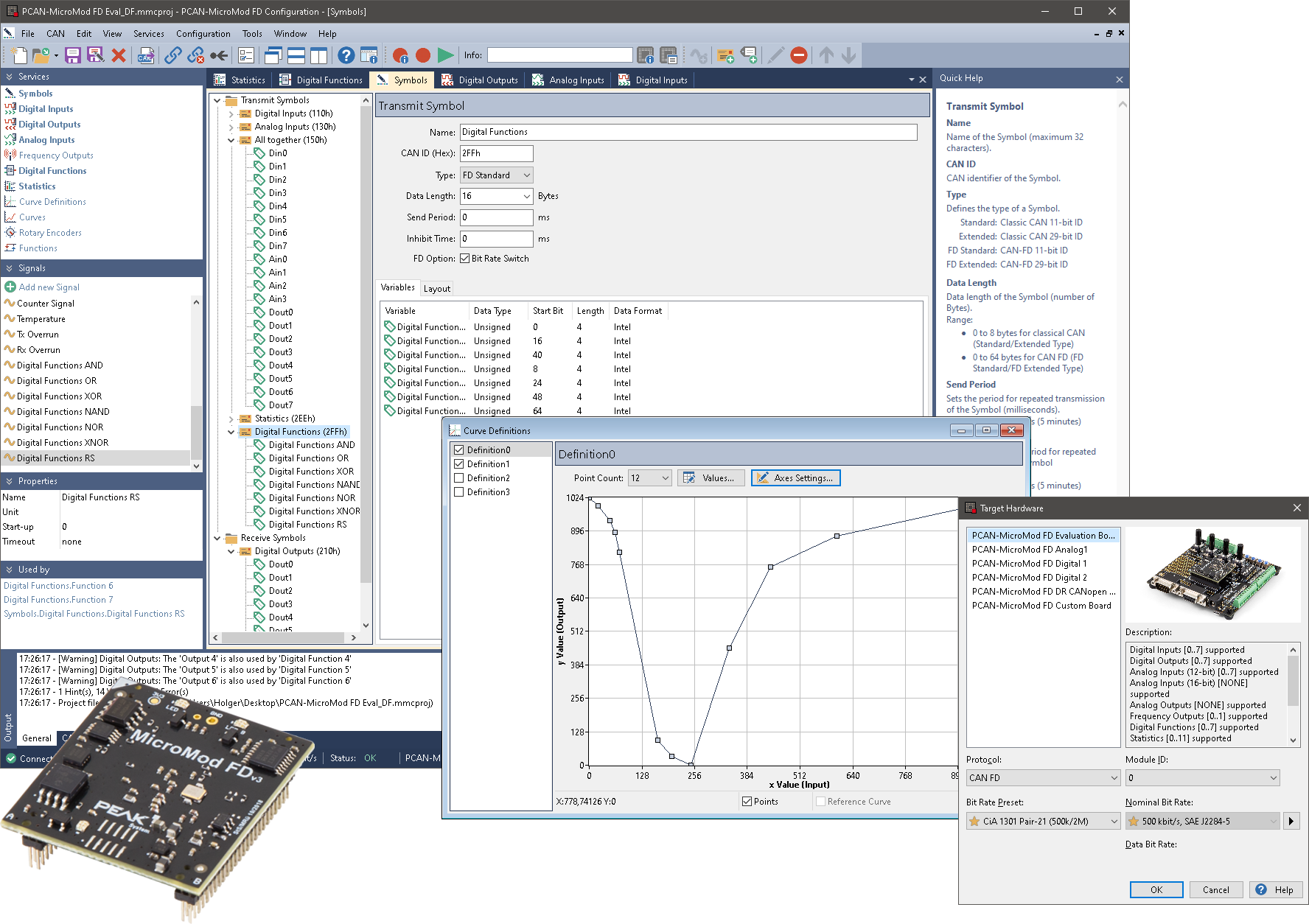
The configuration of products with PCAN-MicroMod FD technology is performed via user-friendly Windows® software that is included as standard. With this software, users can not only easily set the I/O mapping to specific CAN IDs, but also implement more advanced logic using built-in function blocks for data processing. This makes it possible to process complex signals locally before placing them on the CAN bus. The configuration made on the computer is transferred to the MicroMod FD via the CAN bus. Subsequently, the module functions completely independently as an independent CAN node within the network.
< ?php genPopUpImage ( 'mmcfio', $loc . 'peak-system-pcan-micromod-fd-config-io.png', 'PCAN-MicroMod FD I/O Configuration' ) ?>In the configuration software, the Module ID is used to uniquely identify each MicroMod. This allows multiple MicroMod modules to function simultaneously on a single CAN network without conflicts. Each module receives and transmits only the messages corresponding to its configured ID and associated CAN ID mapping.
With the module ID, a maximum of 16 devices can be assigned in a CAN network.
OS Modes
Standaard, CANopen, J1939 of Custom
PCAN products with PCAN-MicroMod FD technology can be used in various operating modes, depending on the firmware and model, with support for the CAN (FD) or CANopen (FD) communication protocols. An extensive configurable CAN I/O application is present by default; CANopen or CANopen FD can be activated with a license key. Additionally, this standard firmware can be replaced by J1939 or custom-developed firmware.
| Product | CAN CAN FD |
CANopen CANopen FD |
Custom Firmware |
|---|---|---|---|
| PCAN-MicroMod FD Evaluation | |||
| PCAN-MicroMod FD Analog 1 | |||
| PCAN-MicroMod FD Digital 12 | |||
| PCAN-MicroMod FD ECU 1 | |||
| PCAN-MicroMod FD DR CANopen Digital 1 1 |
|||
| PCAN-MicroMod FD Custom Motherboard |
= Alternative Operation Mode
= Not supported Operation Mode
1 MircoMod FD is integrated into the PCB for these products, and no use is made of the plug-in board.
Standard firmware for CAN and CAN FD
| Features |
|
|---|---|
| Prerequisite |
|
| Activation |
|
| Configuration |
|
CANopen and CANopen FD with standard firmware
| Features |
|
|---|---|
| Prerequisite |
|
| Activation |
|
| Configuration |
|
J1939 and J1939 FD firmware
| Features |
|
|---|---|
| Prerequisite |
|
| Activation |
|
| Configuration |
|
| Note |
|
Operation with a custom firmware
Various PCAN-MicroMod FD products can be freely programmed with the help of the free development package for
ARM-based products. The included programming examples facilitate the implementation of own solutions.
Note: In the future, this option will also be available for other PCAN-MicroMod FD products.
MicroMod FD Configuration
Graphical configuration
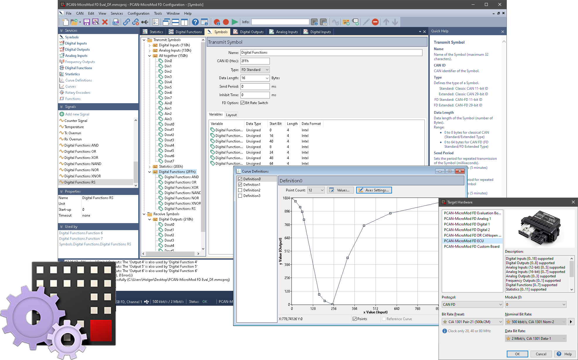
The PCAN-MicroMod FD plug-in module is a universal solution for integrating a CAN FD interface and I/O functionality. Products with PCAN-MicroMod FD technology can be configured using the Windows® software PCAN-MicroMod FD Configuration.
The integrated configuration is transmitted to the PCAN-MicroMod FD via the CAN bus. The module then operates as an independent CAN node with the failed functionality. Multiple modules can be configured independently of each other within a single CAN network.
Features
- Software for configuring PCAN-MicroMod FD based hardware
- Product-specific configuration options due to using predefined hardware profiles
- Setting up the CAN interface by selecting the transmission standard (CAN or CAN FD) and the corresponding bit rates
- Definition of incoming and outgoing CAN messages
- Periodic or event-triggered transmission of CAN messages
- Utilization of Signals for the temporary storage of analog and digital inputs and outputs as well as various status information
- Mapping of the Signals to the data of the CAN messages
- Signal processing with functions and services:
- Scale and Offset function
- Logical linking of digital inputs
- Processing of Signal values via characteristic curves or mathematical calculation operation
- Direct evaluation of rotary encoders - Configuration data transmitted via CAN (PEAK CAN interface required)
- Selective configuration several devices in a CAN network based on the module ID
- Existing configurations can be read out via CAN for further processing
- Export of the CAN message definition as a Symbol file for use with other PEAK-System products like for example PCAN-Explorer
- Switching between CAN and CANopen operating mode
Remark: For the CAN bus connection a PC CAN interface from PEAK-System is required.
Firmware Development Package
PEAK-DevPack
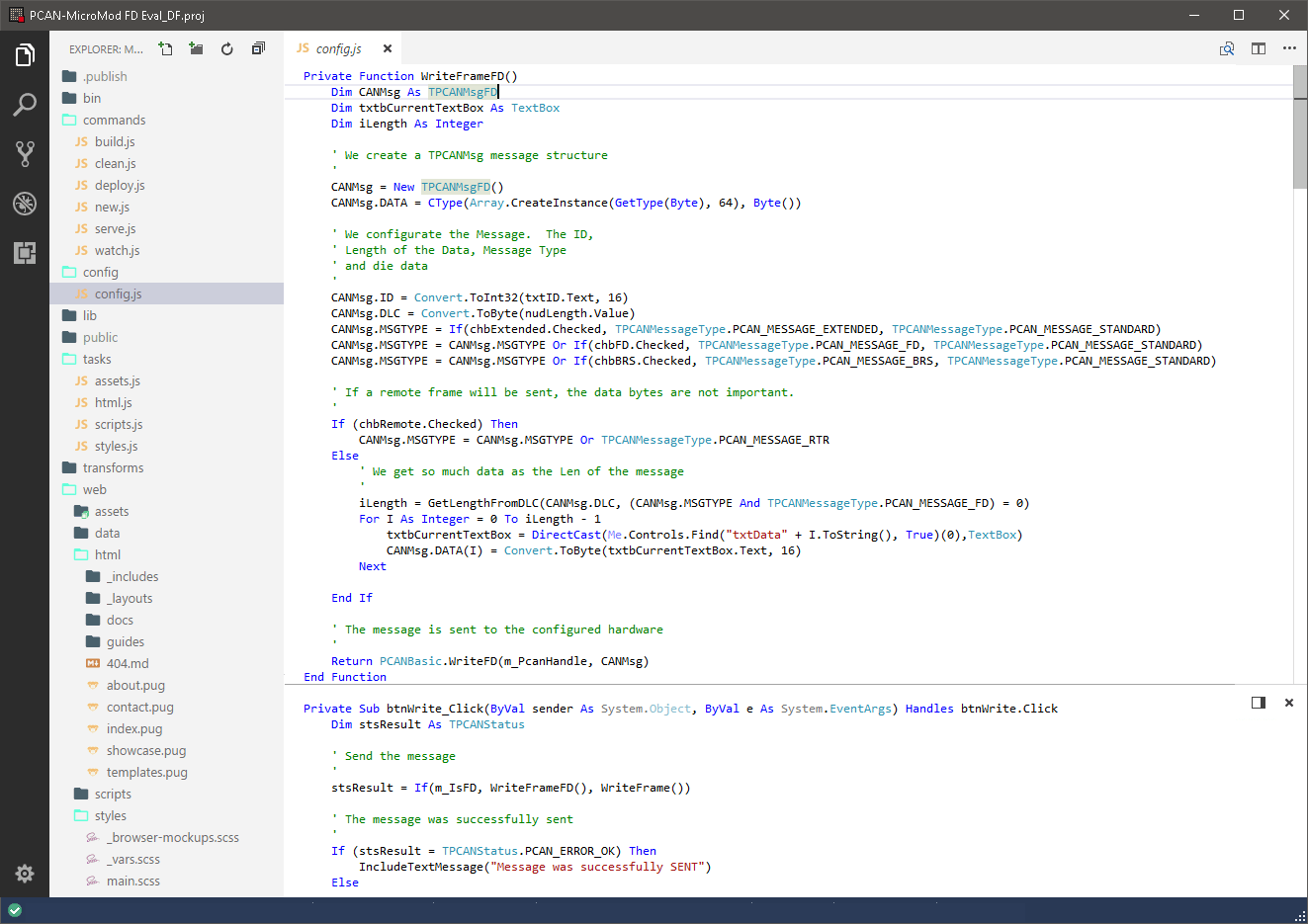
With the help of the PEAK-DevPack development package, custom application-specific firmware for PEAK-System programmable hardware products can be developed. Examples are available for every supported product. The Firmware Development Package works with Visual Studio Code® and the GCC ARM Embedded toolchain, for Windows® 11 or 10.
Currently, PEAK-DevPack supports the following PEAK products: PCAN-GPS FD, PCAN-MicroMod FD, PCAN-MicroMod FD Evaluation Board, PCAN-MicroMod FD Analog, PCAN-MicroMod FD Digital, PCAN-MicroMod FD ECU, PCAN-Router , PCAN-Router DR, PCAN-Router FD, PCAN-Router Pro, PCAN-Router Pro FD, PCAN-RS-232 en PCAN-RS-232 FD
Examples are included for each of these products.
FAQ
-
Is there a CAN terminating resistor built into the PCAN-MicroMod FD Evaluation Board?
Yes, a terminating resistor is built in, but it is disabled by default. It can be turned on or off using a small switch by possibly opening the housing.
-
Can I order on account?
Yes, that's definitely possible! Most customers place their orders through a Purchase Order.
First request a quote and then send the purchase order (PO) by email, simply from your own purchasing system. For first time buyers, we may ask additional questions in order to perform a credit check. Please contact us if you require our company details for registration in the purchasing system.
For security reasons, customers located in, or wishing to ship to, countries outside the Benelux must always pay in advance. -
Why are all prices available upon request?
The online webshop is still under construction. As soon as it is available, all prices will naturally be visible.
However, everything is of course available, and we would be happy to inform you about prices and delivery times. Please contact us or give us a call. We have over 30 years of experience with CAN. We are happy to help you and offer you immediate practical advice or support.
Part number(s)
| IPEH-003081 | PCAN-MicroMod FD Evaluation Board 1x CAN FD, Switchable Bus Termination Country of Origin: Germany HS Code: 9031900000 |
|
| IPEH-003082 | PCAN-MicroMod FD Evaluation Kit 1x CAN FD, Switchable Bus Termination Country of Origin: Germany HS Code: 9031900000 |
Options(s)
-
There are some useful options available for the PCAN-MicroMod FD Evaluation Board

Termination adapter CAN/ CAN FD
CAN-bus termination resistor
PCAN-Cable 1 & 2
Connection Cable for CAN and CAN FD
D-Sub 9 connector CAN/ CAN FD
D-Sub 9 connector with switchable termination resistor
PCAN-T-Adapter
Adapters for a Tap Connection on to CAN or CAN FD
PCAN-Adapter D-Sub to Screw Terminals
D-Sub Adapter for Loose CAN Cable Ends
Scope of Supply
PCAN-MicroMod FD Evaluation Board
- 1x PCAN-MicroMod FD
- 1x USB connector cable
- CANopen license for one PCAN-MicroMod FD
- Manual and schematic in PDF
- PCAN-MicroMod FD Configuration for Windows® 1
- Development package with GCC ARM Embedded, flash program
PCAN-MicroMod FD Evaluation Kit
- Everything as in the Alles zoals bij het PCAN-MicroMod FD Evaluation Board
- 1x CAN interface PCAN-USB FD
- 1x CAN cable with bus termination (2m) PCAN-Cable 2
Interested?
Are you interested in the PCAN-MicroMod FD Evaluation Board? Request a quote without obligation. Would you like more information? Send an email to -Hidden- or visit our contact page. You can also call us at -Hidden-.
Twincomm has over 30 years of experience with CAN. We are happy to help you and offer you immediate practical advice or support.

