

J1939 Module
J1939 Module
The J1939 module allows the processing and interpretation of the J1939 transport protocol as well as the interpretation of diagnostic messages. Proprietary application messages can be interpreted if a user defined database with Parameter Group and Suspect Parameter definitions is provided. Such a database can be e.g. a XML file generated by the Ixxat SAE J1939 Designer.
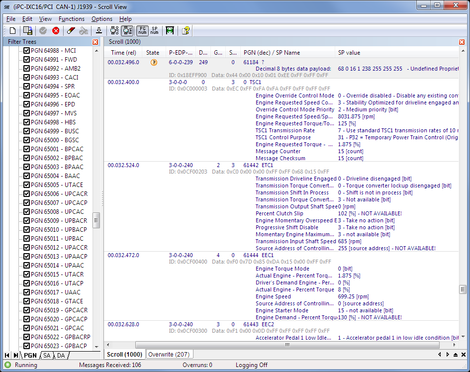
To clearly arrange displayed J1939 messages, it is possible to set filters for Parameter Group Numbers as well as Source and Destination Addresses. Processing/documentation of the received messages can be made permanent or on command by a CSV export to an ASCII file.
CAN, CAN FD, LIN Analysis
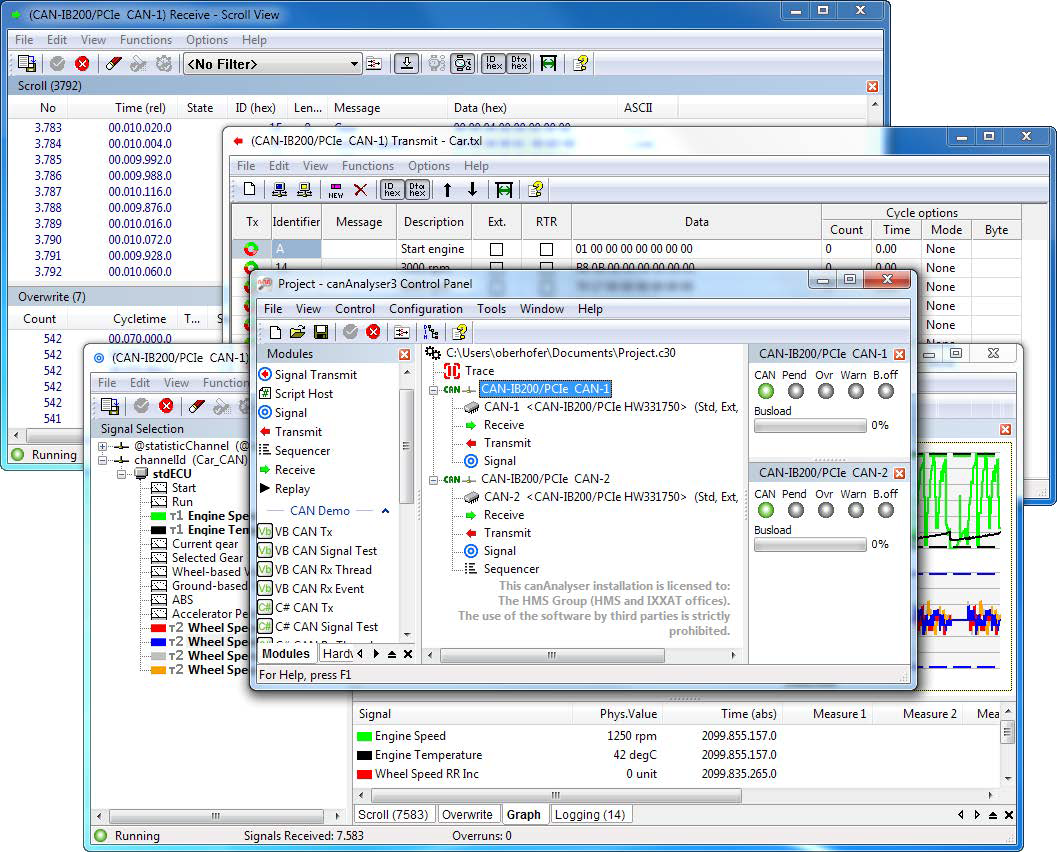
The canAnalyser is based on a modular concept: communication is handled by the control panel, to which various client applications, known as analysis modules, can be connected. The analyzer features a receive module, a send module, a trace module, a playback module, a signal module, a signal send module, a sequencer module, and a script host module.
CANopen and J1939 protocol interpretation modules are also available.
The control panel and the various modules offer the following functionality.
Configuration and use
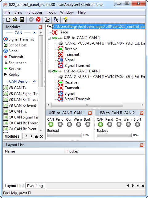
The control panel of the canAnalyser is the central element for configuration. Supported by a Wizard, the required CAN interface is selected and the CAN controller on the board is configured. It also defines which function modules are assigned to the CAN controllers. The configuration is clearly displayed in the form of a tree and the module assignment occurs intuitively by means of drag and drop. Each CAN bus can be assigned a database.
Receiving and displaying CAN messages (Receive Module)
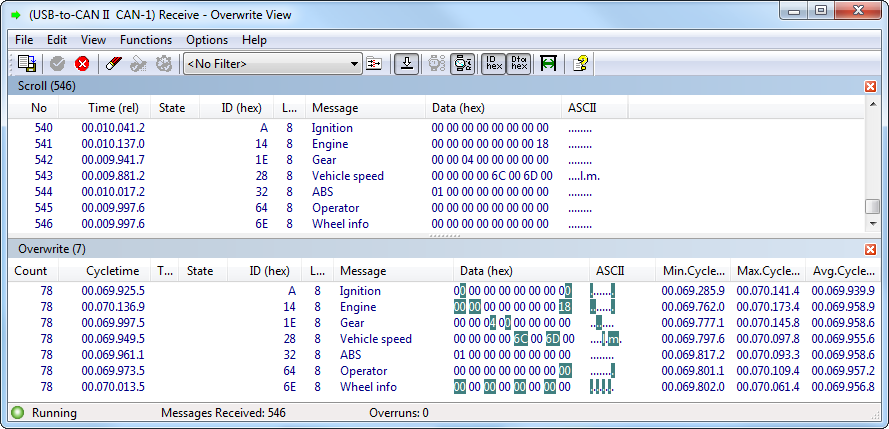
The CAN messages transmitted on the CAN bus can be displayed online in different ways. Either all messages or only certain ones, selected via an adjustable filter, are displayed. Messages can be displayed in two ways. In scroll mode, the messages are displayed together with the time of reception one after the other in a list. This form of display is particularly suitable for monitoring message sequences. On the other hand, in the overwrite mode the messages received are listed according to the identifier and permanently overwritten with the incoming data. Each message is assigned a counter, which displays the commonness of its transmission. Here the altered byte is highlighted in color. With the additional cycle time monitoring, the regularity of reception is observed.
For further monitoring of certain message groups, the receive module can be started multiple times, where each instance can display one section of the CAN data flow.
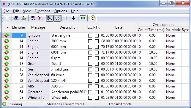
Transmission of CAN-messages (Transmit Module)
Messages to be transmitted can be arranged by the user in a message table. Individual entries from this table can be transmitted once or cyclically. The table contains both the definition of the message (identifier, data bytes, RTR bit) and a description of the message. The data entry can be either decimal or hexadecimal. For messages to be transmitted cyclically, cycle times of 250 us (depending on the used hardware) to 100 s can be specified. In cyclic transmission mode, identifiers or data contents can be incremented automatically.
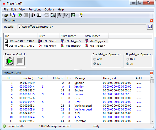
Recording CAN messages (Trace Module)
With the trace module all received messages and error frames are recorded directly onto the hard disk. The recording can be started and stopped via the trace control. In addition, trigger conditions for starting and stopping as well as filters for the CAN messages to be recorded can be defined for each bus. A trace can be viewed at any time and can be reloaded into a system offline for analysis by specifically configured analysis modules, or, online with the aid of the sequence module (limited number of messages).
Play-back of Trace Files (Replay Module)
The Replay Module enables the play-back of trace files. In online mode the messages can be send to the CAN network and received via self reception, in offline mode the messages can be distributed to the connected canAnalyser modules.
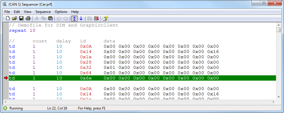
Transmitting message sequences (Sequencer Module)
During the development of CAN devices, functions, protocols and complete systems situations can be tested by transmitting message sequences. Unavailable devices can also be simulated. The message sequences are created with a few easy to learn commands (such as transmitting a message, waiting for a message, pause with specified duration, repeat, user input) via an integrated editor and then executed at the push of a button.
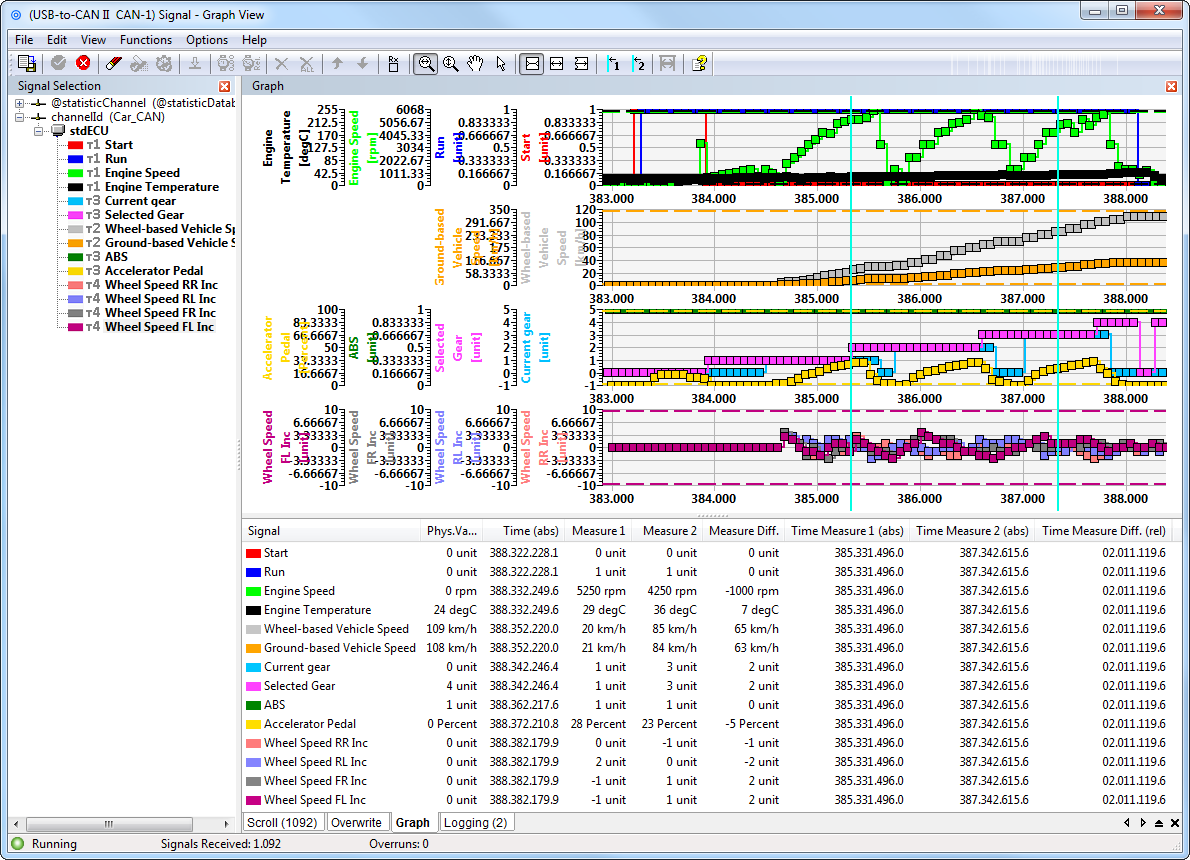
Symbolic interpretation and display of transmitted process variables (Signal Module)
Beyond the display of the receive module, not only is the identifier of a CAN message with a symbolic name displayed, but the complete contents of the message are also extracted and displayed as signals (physical values) based on the interpretation rules stored in the database.
Whether in scroll mode or in overwrite mode, the signals contained in a CAN message can be displayed with the signal module. Messages and signals can be activated and deactivated individually, i.e., excluded from interpretation.
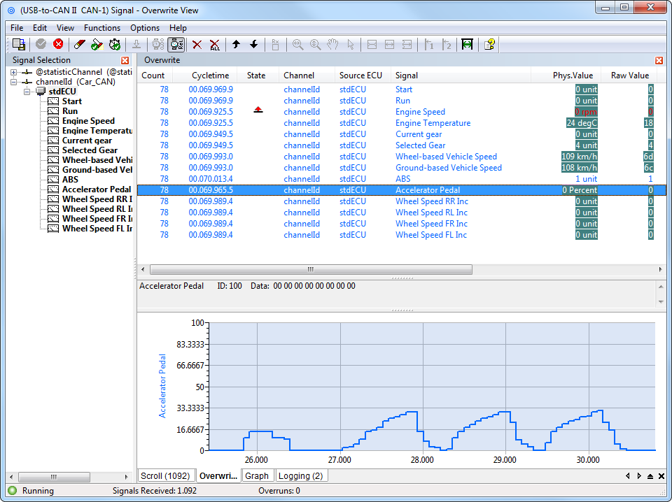
Data contents of CAN messages are displayed in the graphic module in a window over the time axis. The information to be displayed, such as name and unit is automatically taken from the database allocated to a CAN bus. The data is displayed in real time, where a maximum of 16 signals per graphic window are distributed over up to 4 time axes. In addition, the current value of a signal is displayed numerically. With the aid of a metering bar, specific values can be determined and evaluations carried out.
Scripting Host
The Scripting Host provides a powerful interface that combines the advantages of graphic Windows programs with the flexibility of scripts. By using the Scripting Host the canAnalyser can be quickly and easily adapted to specific measuring and analysis tasks. This allows the user to simulate devices and protocols or to test existing devices in the simulated restbus and to put them into operation. Specific test environments can be easily created using any Windows interface components. The Scripting Host supports the standard script languages C# and Visual Basic .NET. The incorporation of DLLs also enables the integration of further modules.
Programmability
Due to the open programming interface, the canAnalyser can be extended by the user's own modules or user interfaces. With common Windows development systems (e.g. Visual Studio.NET), new, independent modules can be developed and added to the canAnalyser. It is possible for users to create interfaces for their systems or for certain devices or tools with system specific analysis functions.
Editor for the project databases
The basis for the interpretation and symbolic display of the data transmitted in the CAN message is the project database. In this, a CAN message is first assigned a name according to its identifier.
CANopen Module
CANopen Module
All received messages can be displayed one after the other in a list (scroll mode), or listed according to the identifier (overwrite mode), permanently overwritten with new incoming data and with highlighting of altered bytes and reception statistics. It is possible to filter the messages loss-free and dynamically according to both their node number and their message type as well as to configure the collor coding of the messages. Furthermore, the interpreted messages can be recorded to a file.
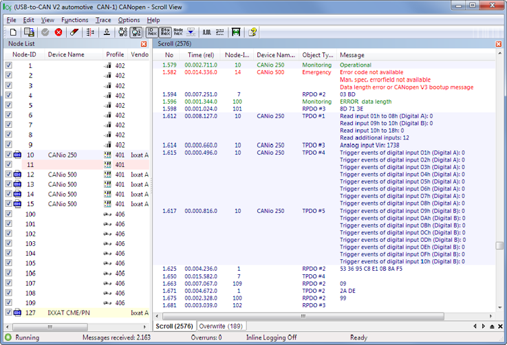
An SDO transfer is displayed with index and subindex and the symbolic name of the addressed object dictionary entry. Any abort code which may occur is correctly displayed. The SDO data can either be displayed during the transmission as subsequence or afterwards, considering the type of data, as entity. The PDO content is decoded according to the individual device or profile description.
The interpretation of the layer-2 messages is based on a network model, describing all nodes in the CANopen network. The model is generated either by loading the device description files (EDS, DCF, XDD), by a simple profile as-signment, via online network scan or manually. Furthermore, the project files of the Ixxat CANopen ConfigurationStudio are supported.
